
Are you tired of your factory car stereo and craving an upgrade? Installing a new Pioneer car deck can drastically improve your in-car entertainment experience, offering features like Apple CarPlay, Android Auto, enhanced audio quality, and more. However, the thought of dismantling your dashboard can be daunting. Fear not! This comprehensive guide will walk you through the process of safely removing your old car stereo and installing a brand new Pioneer head unit, focusing on the essential tools and techniques you’ll need for a smooth and successful upgrade. While the process might seem intricate, with the right approach and tools, including a Pioneer Car Deck Removal Tool or trim removal tools, you can achieve a professional-level installation in your own garage.
Tools and Parts for a Seamless Stereo Upgrade
Before you even think about touching your dashboard, gathering the right tools and parts is crucial. Having everything at hand will not only make the process smoother but also minimize the risk of damage to your car’s interior. For this guide, we’ll assume you’re upgrading to a Pioneer SPH-DA120 AppRadio (or similar double DIN unit) in a Nissan 350Z, but the general principles apply to most car stereo installations.
Here’s what you’ll need:
-
Essential Tools:
- Screwdrivers: A set of Phillips and flat-head screwdrivers in various sizes. Magnetic tips are highly recommended to prevent dropped screws in hard-to-reach places.
- Trim Removal Tools: This is where your pioneer car deck removal tool (or a set of plastic trim removal tools) comes in. These tools are designed to safely pry off plastic trim panels without scratching or breaking them. Metal tools can cause damage, so plastic is preferred.
- Soldering Iron, Solder, and Heat Shrink Tubing: For secure and insulated wire connections. Crimping tools and bullet connectors are an alternative if you prefer not to solder.
- Wire Strippers/Crimpers: For preparing wires for soldering or crimping.
- Multimeter (Optional but Recommended): For testing wire continuity and voltage, especially useful for troubleshooting.
-
Parts Required (Specific to Nissan 350Z and Pioneer Head Unit, adjust for your car and stereo):
- Steering Wheel Control Interface: To retain functionality of your steering wheel audio controls with the new Pioneer unit. For Nissan 350Z Bose systems, the InCarTec 29-674 (or equivalent) is often used.
https://incartec.co.uk/product/Nissan-350Z-Murano-10-6-16-Pin-audio-steering-wheel-control-interface-29-674 - Pioneer Patch Lead for Steering Wheel Control Interface: Connects the interface to your specific Pioneer head unit. InCarTec 29-007 (or equivalent) for Pioneer 29 series SWC.
https://incartec.co.uk/product/PIONEER-patch-lead-for-29-series-SWC-29-007 - Double DIN Radio Fascia Adapter: Provides a clean and factory-look finish for your double DIN Pioneer stereo in the Nissan 350Z dash. InCarTec 50-256 (or equivalent) for Nissan 350Z (2003-2010) in matte black.
https://incartec.co.uk/product/Nissan-350Z-2003-2010-double-DIN-car-radio-fascia-adapter-panel-MATT-BLACK-50-256 - Wiring Harness Adapter: To connect your Pioneer stereo to the Nissan 350Z factory wiring without cutting any original wires. This is usually included with the steering wheel control interface or purchased separately.
- Pioneer Stereo Head Unit: Like the Pioneer SPH-DA120 AppRadio or your chosen model.
- Antenna Adapter (Possibly): Depending on your car and stereo, you might need an antenna adapter to connect the car’s antenna cable to the Pioneer unit.
- Steering Wheel Control Interface: To retain functionality of your steering wheel audio controls with the new Pioneer unit. For Nissan 350Z Bose systems, the InCarTec 29-674 (or equivalent) is often used.
Understanding the Wiring Harnesses
Before diving into the physical installation, let’s familiarize ourselves with the wiring harnesses. This will save you time and frustration later.
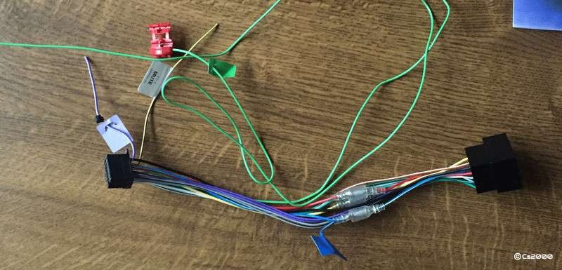
The Steering Control Interface & ISO Connector lead typically has these sections:
- ISO Connector (Red Section in Original Article Description): This adapts the Nissan 350Z factory wiring (white sockets) to the standard ISO connector (black plug). Your Pioneer head unit’s wiring harness will then connect to this ISO connector. It often includes a black wire with an eyelet for grounding – this must be connected to a chassis ground in your car.
- Steering Wheel Control Module (Blue Section): This module interfaces with your car’s steering wheel control system. It connects to the car’s wiring (white plug) and outputs steering wheel control signals.
- Steering Wheel Control Output (Green Section): Usually a jack plug, this connects to the back of your Pioneer head unit to transmit steering wheel control signals.
The Pioneer Head Unit Wiring Harness (included with your Pioneer stereo) will vary by model, but common wires to identify include:
- Green Wire (Long): Parking brake wire. Designed to disable certain head unit functions unless the handbrake is engaged. Many installers bypass this for convenience.
- Purple & White Striped Wire (Short): Reverse camera input trigger wire. Connect to your reverse light circuit to automatically switch to a backup camera display when reversing (if you have a camera installed).
- Red & Yellow Wires (with Bullet Connectors): Power wires. One for constant 12V power (for memory) and one for switched 12V ignition power. If your head unit stays on when the car is off, you might need to swap these connections.
- Blue & White Striped Wire (with Bullet Connectors): Remote turn-on wire. Typically for external amplifiers, but in the Nissan 350Z, it’s used for the power antenna and the factory BOSE amplifier (if equipped).
Wiring Connections: Preparing the Harness
Now, let’s prepare the wiring harnesses before heading to the car.
-
Connect the ISO Connector: Take the Pioneer head unit harness and the InCarTec loom (or equivalent). Locate the black plug on the InCarTec loom that matches the top section of the double-stacked connector on the Pioneer harness (the section with fewer pins). Connect them together.
-
Modify the Harness (Nissan 350Z Specific Steps):
-
Power Antenna Connection: Locate the blue & white striped wires on both the InCarTec and Pioneer harnesses. These need to be connected for the power antenna (and BOSE amp) to work. Use bullet connectors, solder, or crimp connectors to join them.
-
Parking Brake Bypass (Optional and with Caution): If you choose to bypass the parking brake safety feature (allowing video playback or certain functions while driving – check local laws and regulations first), find the green parking brake wire on the Pioneer harness and the black ground wire on the same harness. Connect these two wires together by twisting, soldering, and insulating with heat shrink. Exercise caution and be aware of potential safety and legal implications.
-
BOSE Amplifier Volume Fix (Nissan 350Z BOSE Systems): Nissan 350Z models with the BOSE sound system may experience lower volume output with aftermarket stereos when using only the RCA pre-outs. This requires a modification to route speaker-level signals to the BOSE amplifier. Refer to online guides like the “Buster’s RCA Headunit Volume Fix” for detailed instructions if needed. This often involves modifying or creating an additional wiring section.
-
With the harness modifications complete, you should have a neatly wired harness ready to connect to your Pioneer head unit and the Nissan 350Z factory wiring.
Removing the Old Car Stereo: Step-by-Step
Now for the exciting part – removing the old stereo and preparing for the new Pioneer unit. This is where your pioneer car deck removal tool (trim removal tools) becomes invaluable.
-
Prepare the Center Console:
-
Gear Gaiter Surround Removal: Gently pull up on the silver ring around the gear shift gaiter surround. Twist and detach it, then set it aside in the passenger footwell area. Shifting your car into 2nd, 4th, 6th, or Reverse can provide more working space.
-
White Ribbon Cable Disconnection: Locate the white ribbon cable connected to the center dash trim. Press down firmly on the clip on the connector and gently pull the ribbon cable away from the unit. Be careful as these ribbon cables can tear easily.
-
Lower Dash Screw Removal (Gold Screws): Remove the two gold-colored screws located at the lower part of the dash, one on each side. Keep these screws safe.
-
Lower Dash Screw Removal (Head Unit Bracket and A/C Control Screws): Locate the four screws at the lower part of the dash again. The gold screws (usually closer to the center) secure the head unit mounting brackets, and the black screws (outer ones) hold the A/C control box. Remove all four screws. Let the A/C control unit hang freely for now.
-
Cubby Hole Hidden Screw Access: Open the cubby hole in the center dash. Lift out the rubber mat inside. You’ll see two screws. Remove these screws (usually black). This plastic piece is part of the cubby door locking mechanism and also hides two more screws we need to access. Lift out this plastic piece.
-
Hidden Screw Removal (Behind Cubby Hole): Now you can see the last two hidden screws, usually gold in color. Use a magnetic screwdriver to remove these, as they are easy to drop and lose behind the dashboard. Important Note: The bracket these screws secure is grounded. This is a convenient grounding point for your new head unit.
-
-
Remove the Center Dash Trim: The center dash trim should now be free. Start pulling it out slowly and carefully from the bottom, working your way upwards. As you reach the top, you’ll find a white connector for the center pod gauges. Disconnect this connector by pressing the plastic lock (facing the windshield). Remove the entire center dash trim piece.
-
Disconnect the Old Head Unit: With the center dash removed, you’ll see the back of the factory BOSE head unit. Disconnect the three white wiring plugs by pressing down on their clips and pulling them out. The black antenna connector simply pulls straight out.
-
Remove the Old Head Unit from Brackets: Remove the four screws (two on each side) that secure the old BOSE head unit to the car’s mounting brackets. Remove the old head unit from the brackets.
The old car stereo is now completely removed.
Installing the New Pioneer Car Deck: Step-by-Step
With the old stereo out, it’s time to install your new Pioneer head unit.
-
Connect Wiring Harnesses: Connect the prepared wiring harnesses to the Nissan 350Z factory wiring plugs. They are usually keyed to fit only one way. Connect the antenna cable to the new Pioneer head unit. Crucially, connect the ground wire (eyelet) from your new harness. Use one of the screws you removed from behind the cubby hole (as these are grounded points) to secure the ground wire.
-
Install Fascia Adapter: Remove the factory mounting brackets from the removed center dash trim piece. These are held by a single screw on each side. Place the new double DIN fascia adapter into the center dash trim opening.
-
Test the Head Unit: Before fully reassembling, now is a good time to test if everything is working. Turn on the car ignition and check if the Pioneer head unit powers on, if you get sound from the speakers, and if the steering wheel controls are functioning. Also, test any other connections like GPS antenna, reverse camera, USB, AUX inputs, etc.
-
Attach Mounting Brackets to New Head Unit: Attach the factory mounting brackets to the sides of your new Pioneer head unit. Use the screws that came with the Pioneer unit, if provided. Refer to the Pioneer head unit’s manual for the correct mounting holes (often labeled by car manufacturer). Don’t fully tighten the screws yet.
-
Install Head Unit Assembly into Dash: Carefully slide the Pioneer head unit with the attached brackets into the fascia adapter opening in the center dash trim. Secure it using the two black screws you removed earlier from the sides of the original head unit location.
-
Adjust and Tighten: Adjust the position of the head unit within the fascia for the best fit and appearance. Once satisfied, fully tighten all screws: the six head unit screws and the two black bracket mounting screws.
Reassembly and Completion
Reassembly is, as they say, the reverse of disassembly.
-
Wire Management: Carefully tuck all the wiring harnesses into the dash cavity behind the head unit. Space can be tight, so take your time to arrange the wires neatly.
-
Reattach Components:
- Position the center dash trim back into the car.
- Guide the metal ‘legs’ at the bottom of the dash trim back into their position behind the white heater control box. Reattach the two lower gold screws.
- Remount the heater control box and secure it with the two black screws.
- Reinstall the two gold screws hidden behind the cubby hole (remember to secure the ground wire with one of these).
- Reconnect the electrical connector for the center pod gauges.
- Reattach the two gold screws at the bottom front of the center dash trim.
- Reinstall the plastic latch mechanism in the cubby hole and secure it with the two black screws. Replace the rubber mat in the cubby hole.
-
Final Check: Ensure everything is securely fastened and all trim pieces are properly in place. Turn on the ignition and double-check that your new Pioneer car deck is working correctly, including sound, steering wheel controls, and any other connected features.
-
Enjoy Your Upgraded Audio: Congratulations! You’ve successfully removed your old car stereo and installed a brand new Pioneer car deck.
Upgrading your car stereo can significantly enhance your driving experience. By using the right tools, like a pioneer car deck removal tool (trim removal tools), and following these steps, you can confidently tackle this DIY project and enjoy the benefits of a modern Pioneer head unit in your car. Remember to always double-check your car’s specific wiring and consult your Pioneer head unit’s manual for any model-specific instructions. Happy listening!