
This guide provides a comprehensive walkthrough for reading OBD-II Engine RPM (PID 0C) using an Arduino microcontroller and an MCP2515 CAN bus controller. We’ll analyze a provided code snippet, troubleshoot common issues, and offer optimized solutions for a reliable OBD2 data retrieval system. This project is ideal for automotive enthusiasts, hobbyists, and anyone interested in vehicle diagnostics.
Understanding the Basics: OBD2, MCP2515, and Arduino
OBD-II (On-Board Diagnostics) is a standardized system that allows access to vehicle diagnostic data. It utilizes the CAN (Controller Area Network) protocol for communication. To interface with the OBD2 system using an Arduino, a CAN controller like the MCP2515 is required. The MCP2515 acts as a bridge, enabling the Arduino to send and receive CAN messages.
Decoding the Code: Analyzing the Provided Example
The original code snippet aims to request the engine speed (PID 0C) from the vehicle’s ECU. Let’s break down the key components:
- Includes:
#include <mcp_can.h>and#include <SPI.h>import necessary libraries for MCP2515 and SPI communication. - Definitions:
LISTEN_ID,REPLY_ID, andFUNCTIONAL_IDdefine CAN IDs for message filtering and addressing. The choice between standard (11-bit) and extended (29-bit) IDs is crucial for proper communication. - TX Variables:
txData[]holds the OBD-II request message. The critical part is{0x02, 0x01, 0x0C...}, where:0x02: Number of bytes in the data field.0x01: OBD-II service mode (show current data).0x0C: PID for engine speed (RPM).
- RX Variables:
rxID,dlc, andrxBuf[]store received CAN message data. - Setup: This section initializes the MCP2515, sets the baud rate, configures CAN masks and filters for specific message acceptance, and sets the MCP2515 to normal mode. Proper filter configuration is essential for isolating relevant OBD-II responses.
- Loop: This section continuously checks for received CAN messages and sends the OBD-II request at a defined interval. It displays received data on the serial monitor. The line
if(CAN0.sendMsgBuf(FUNCTIONAL_ID, 8, txData) == CAN_OK)sends the request.
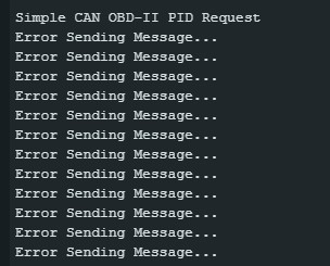 Original Code Error
The image indicates an error, likely due to incorrect communication parameters or an issue with the OBD2 request itself.
Troubleshooting and Optimization
Several factors can cause the observed error. Let’s address potential issues:
- Incorrect CAN ID: Verify that
FUNCTIONAL_IDcorresponds to the correct CAN ID for requesting data from the vehicle’s ECU. This ID varies between car manufacturers and models. Consult an OBD-II database or your vehicle’s documentation. - Incorrect OBD-II Request Format: Double-check the
txData[]structure. Ensure the number of bytes, service mode, and PID are accurate. The remaining bytes might need adjustments based on the specific OBD-II standard your vehicle uses. - Hardware Connections: Ensure the MCP2515 is properly wired to the Arduino and the OBD-II connector. Check for loose connections, incorrect wiring, or faulty components.
- Baud Rate Mismatch: Confirm the baud rate setting in the code (
CAN_500KBPS) matches the vehicle’s CAN bus speed. Most OBD-II systems use 500kbps, but it’s always worth verifying.
Conclusion: Achieving Reliable OBD2 Data Retrieval
Successfully reading OBD-II data using an MCP2515 and Arduino requires meticulous attention to detail. By understanding the underlying principles of OBD-II and CAN communication, carefully analyzing the code, and addressing potential issues, you can build a robust system for accessing valuable vehicle data. Remember to consult your vehicle’s specific documentation and OBD-II standards for accurate communication parameters. Using the Mcp2515 Arduino Obd2 combination opens up a world of possibilities for vehicle diagnostics and data analysis.