
Creating your own USB to OBD2 cable can be a rewarding experience, saving you money and allowing for customization. This guide provides a detailed walkthrough of the process, perfect for DIY enthusiasts. While I’m not a professional mechanic, this method worked for me, and hopefully, it will for you too. Remember, you’re undertaking this project at your own risk.
Gathering Your Supplies
Before you begin, ensure you have the following tools and parts:
- Tools:
- Wire strippers/cutters
- Needle-nose pliers
- Soldering iron (recommended)
- Molex crimping tool (optional)
- Parts:
- 4-pin connector (22-16 AWG wire size, 1.3-1.7mm insulation/seal size)
- OBD-II Cable (female connector)
- Wire (optional, if you have spare wire and only need the OBD-II connector)
You can potentially save money by using spare wire and purchasing only the female OBD-II connector. However, ensure you know the wire gauge to select the appropriate 4-pin connector.
Identifying the Necessary OBD2 Wires
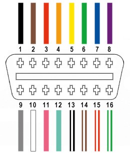
A standard OBD2 connector (OBD2C) has 16 wires. For this project, we only need four:
- Pin 4: Chassis ground (orange wire)
- Pin 6: CAN (J-2234) High (green wire)
- Pin 14: CAN (J-2234) Low (brown with white stripe wire)
- Pin 16: Battery power (green with white stripe wire)
Building Your DIY USB to OBD2 Cable: Step-by-Step Instructions
Step 1: Preparing the Wires
Remove the outer sheath and shielding from the OBD2C cable, separating the four necessary wires (orange, green, brown/white, and green/white). Secure the remaining wires with a zip tie to prevent interference.
Step 2: Prepping the 4-Pin Connector
Since the OBD2C wires (26 AWG) might be thinner than the 4-pin connector (4PC) pins (designed for 22 AWG), strip about 3/8″ of insulation from each wire, fold it over, and twist to increase thickness. Slide a rubber seal (included with the 4PC) over each wire.
Step 3: Connecting the Wires to the Pins
Insert the exposed wire into the front prongs of the 4PC pin. You might need needle-nose pliers to hold the wire in place.
Step 4: Securing the Connection
Soldering the wire to the pin provides a secure connection. If you have a Molex crimping tool, you can crimp the connector instead.
Step 5: Securing the Seal
Slide the rubber seal up between the back prongs of the pin and crimp or use pliers to fold the prongs over the seal.
Step 6: Twisting Wire Pairs
Pair and twist the following wires:
- Orange (Pin 4) and Green/White (Pin 16)
- Green (Pin 6) and Brown/White (Pin 14)
Step 7: Connecting to the 4-Pin Connector
Insert the pins into the 4PC in the following order:
- Brown/White (Pin 14) into slot A
- Green (Pin 6) into slot B
- Green/White (Pin 16) into slot C
- Orange (Pin 4) into slot D
Push each pin through the back of the connector until you hear a click. Use pliers to assist if necessary.
Final Product and Testing
Your Diy Usb To Obd2 Cable is complete!
Test the cable by connecting it to your vehicle and using an OBD2 software.