
Connecting your computer to your car’s onboard diagnostics (OBD) system can be a powerful tool for diagnosing and troubleshooting issues. While commercial USB to OBD2 adapters are readily available, building your own can be a rewarding and cost-effective project. This guide provides a detailed walkthrough of creating a Diy Usb To Obd2 adapter, perfect for car enthusiasts and DIYers.
This project involves some basic soldering and wiring, so familiarity with these skills is recommended. However, the steps are straightforward and easy to follow, even for beginners.
Gathering Your Materials
Before starting, ensure you have the following tools and parts:
- Tools:
- Wire strippers/cutters
- Needle-nose pliers
- Soldering iron (recommended)
- Molex crimping tool (optional, but recommended)
- Parts:
- 4-pin Molex connector (22-16 AWG wire size, 1.3-1.7mm insulation/seal size)
- Female OBD-II connector with pigtail wires
- USB to Serial adapter (e.g., FTDI chip-based)
- Heat shrink tubing (optional)
You can source these parts from various online electronics retailers or local automotive parts stores.
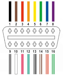
Identifying the OBD2 Pins
The standard OBD2 connector (OBD2C) has 16 pins, but we only need four for this project:
- Pin 4: Chassis Ground (Orange wire)
- Pin 6: CAN High (J-2234) (Green wire)
- Pin 14: CAN Low (J-2234) (Brown with white stripe wire)
- Pin 16: Battery Power (Green with white stripe wire)
Building the Adapter
Step 1: Preparing the Wires
Separate the four necessary wires (pins 4, 6, 14, and 16) from the OBD2 connector pigtail. Strip approximately 3/8″ of insulation from the ends of each wire. If the wires are thinner than the 4-pin connector pins, twist the exposed strands together to increase their thickness. Slide a rubber seal (included with the 4-pin connector) over each wire.
Step 2: Connecting the Wires to the 4-Pin Connector
Insert the exposed wire into the front prongs of the corresponding pin on the 4-pin connector. Solder the wire to the pin for a secure connection. If you have a Molex crimping tool, you can crimp the connector instead of soldering.
Step 3: Securing the Connection
Fold the back prongs of the connector over the rubber seal to secure the wire and provide strain relief. You can use needle-nose pliers to help fold the prongs.
Step 4: Pairing and Twisting the Wires
Pair and twist the following wires together:
- Pin 4 (Orange) and Pin 16 (Green/White)
- Pin 6 (Green) and Pin 14 (Brown/White)
This helps reduce signal interference. You can use heat shrink tubing to further secure the twisted pairs.
Step 5: Connecting to the USB to Serial Adapter
Connect the wires from the 4-pin connector to the corresponding pins on your USB to Serial adapter. Consult the adapter’s documentation for the correct pinout. Common configurations use:
- TXD: Pin 6 (Green)
- RXD: Pin 14 (Brown/White)
- GND: Pin 4 (Orange)
- +5V: Pin 16 (Green/White)
Testing the Adapter
Once assembled, connect the adapter to your computer’s USB port and to your car’s OBD2 port. Use a compatible OBD2 software application to verify communication and functionality. You should be able to read diagnostic trouble codes (DTCs) and other vehicle data.
This DIY USB to OBD2 adapter offers a budget-friendly solution for accessing your car’s diagnostic data. While requiring some basic technical skills, the process is relatively simple and can provide a valuable tool for any car enthusiast. Remember to double-check all connections and consult reputable sources for specific wiring diagrams if needed.