This guide provides a detailed walkthrough on how to build your own Diy Obd2 Usb Cable for vehicle diagnostics. This project is perfect for car enthusiasts looking to save money and gain a deeper understanding of their vehicle’s onboard diagnostics system. While I successfully completed this project, remember I’m not a professional mechanic. This guide is for informational purposes only, and you are responsible for any outcomes. Always prioritize safety and consult a professional if needed.
Gathering Your Supplies for Your OBD2 Cable
Before you begin, ensure you have the following tools and parts:
-
Tools:
- Wire strippers/cutters
- Needle-nose pliers
- Soldering iron (highly recommended)
- Molex crimping tool (optional, but makes the job easier)
-
Parts:
- 4-pin connector (ensure it’s compatible with 22-16 AWG wire and 1.3-1.7mm insulation)
- OBD-II Cable (female connector)
- Spare wire (22 AWG recommended) – optional if your OBD-II cable has long enough wires
Understanding the OBD2 Connector Wiring
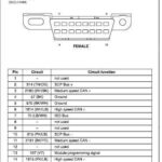
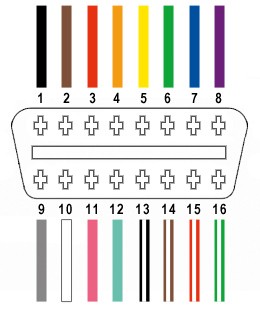
A standard OBD2 connector (OBD2C) has 16 pins, but we only need four for this DIY obd2 usb cable project:
- Pin 4: Chassis Ground (Orange wire)
- Pin 6: CAN High (J-2234) (Green wire)
- Pin 14: CAN Low (J-2234) (Brown with white stripe)
- Pin 16: Battery Power (Green with white stripe)
Building Your DIY OBD2 USB Cable: A Step-by-Step Guide
Step 1: Prepare the OBD2 Cable
Remove the outer sheath and shielding from the OBD2C, exposing the wires. Separate the four wires we’ll be using (pins 4, 6, 14, and 16) and secure the remaining wires with a zip tie to keep them out of the way.
Step 2: Prepare the Wires for the 4-Pin Connector
The wires in the OBD2C might be thinner (e.g., 26 AWG) than the 4-pin connector (4PC) requires (e.g., 22 AWG). If so, strip about 3/8″ of insulation, fold the exposed wire over, and twist it to “thicken” it for a better fit. Slide a rubber seal (included with the 4PC) over each wire.
Step 3: Connect the Wires to the 4-Pin Connector Pins
Insert the exposed wire into the front prongs of the 4PC pin. You might need needle-nose pliers to hold the thin wire in place.
Step 4: Secure the Connection (Soldering Recommended)
Soldering the wire to the pin provides a solid connection. If you have a Molex crimping tool, you can crimp the connector instead.
Step 5: Crimp the Connector (If Not Soldering)
Using needle-nose pliers, carefully fold the prongs over the wire. You can find helpful videos online demonstrating this technique.
Step 6: Secure the Rubber Seal
Slide the rubber seal up between the back prongs of the pin and crimp them over the seal to secure it in place.
Step 7: Twist Wire Pairs
Pair and twist the following wires:
- Pin 4 (Orange) with Pin 16 (Green/White)
- Pin 6 (Green) with Pin 14 (Brown/White)
Step 8: Connect the Pins to the 4-Pin Connector Housing
Insert the pins into the 4PC housing in the following order:
- Slot A: Pin 14 (Brown/White)
- Slot B: Pin 6 (Green)
- Slot C: Pin 16 (Green/White)
- Slot D: Pin 4 (Orange)
Push each pin through the back of the connector until you hear a click.
Finished DIY OBD2 USB Cable
Congratulations! You’ve built your own DIY obd2 usb cable!
This cable can be used with a suitable USB OBD2 adapter for vehicle diagnostics. Remember, always test your connection before relying on it for critical tasks.